Products
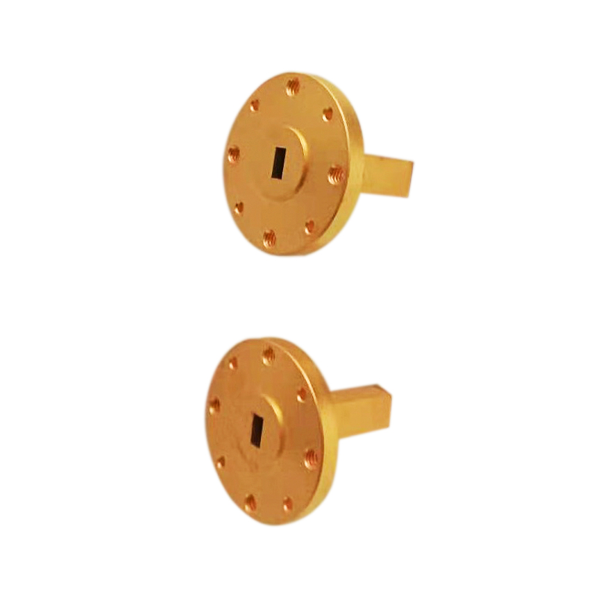
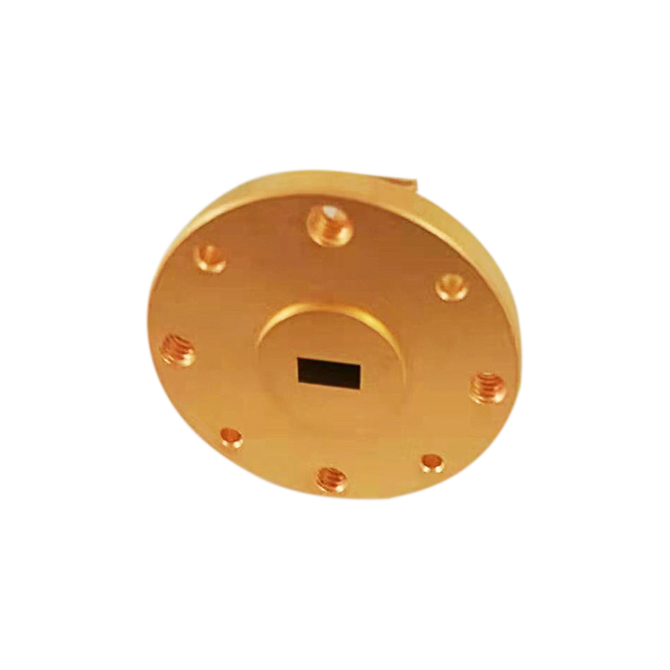
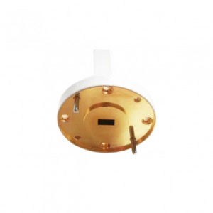
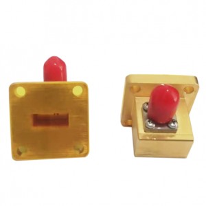
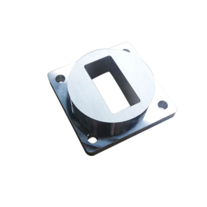
WR15 Rectangular Waveguide Terminal Matched Load 50-75GHz
| Waveguide | WR15 |
| Frequency Range(GHz) | 50-75 |
| VSWR | 1.05Max |
| Average power(w) | 0.3CW |
| Peak power (kw) | 0.1 |
| Flange | FUGP620(UG-3857U) |
| Material | Brass |
| Size(mm) | 30*19.1*19.1 |
| Net Weight(Kg) | 0.02Around |
Product Description
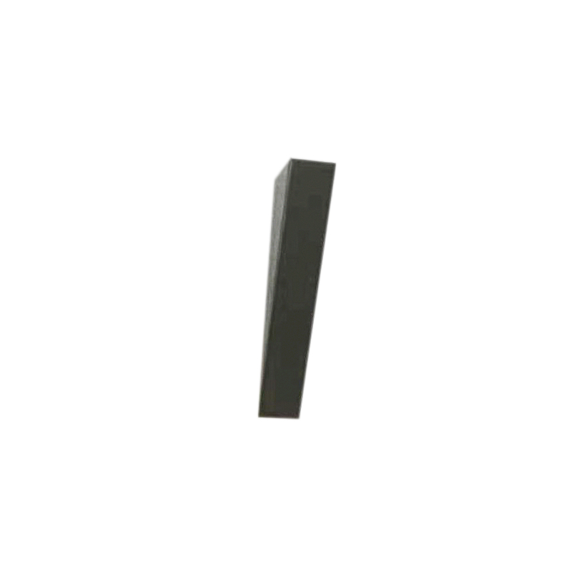
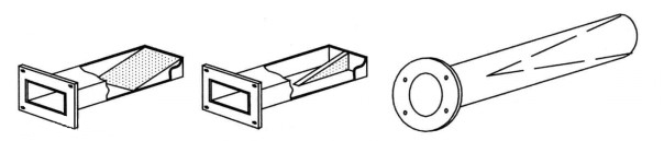
The matching load of the waveguide is a wedge or plate made of lossy materials embedded in the waveguide, as shown in Fig. 1 (a) and (b), and the matching load of the circular waveguide is made of birch, as shown in Fig. 1 (c). Because the material is lossy, the incident wave power is absorbed by it. At the same time, because the electromagnetic field gradually enters the wedge made of lossy material, the reflection is avoided. This kind of terminator can be regarded as a lossy gradual transmission line. Usually, the matching load made of lossy gradient lines with one or more wavelengths is enough to make its input VSWR below 1.01.
Requirements for matching load:
(1) The VSWR is small.
(2) Wide operating frequency band.
(3) High power capacity (heat resistant)
(4) Not easy to puncture.
(5) It is not easy to leak high-frequency energy.
(6) Vibration resistance.
(7) The performance is stable and will not change due to temperature rise, humidity or aging.
Application of matching load:
In addition, the matching load is also commonly used as a false antenna to eliminate space radiation without interfering with other electronic equipment.
|
Modle |
Frequency |
VSWR |
Average power |
Waveguide |
Length |
|
(GHz) |
(Max) |
(W ) |
(mm) |
||
|
XEXA-WL1150 |
1.45~2.20 |
1.05 |
2 |
WR1150 |
320 |
|
XEXA-WL430 |
1.72~2.61 |
1.05 |
2 |
WR430 |
300 |
|
XEXA-WL340 |
2.17~3.30 |
1.05 |
2 |
WR340 |
280 |
|
XEXA-WL284 |
2.60~3.95 |
1.05 |
2 |
WR284 |
260 |
|
XEXA-WL229 |
3.22~4.90 |
1.05 |
2 |
WR229 |
220 |
|
XEXA-WL187 |
3.94~5.99 |
1.05 |
2 |
WR187 |
200 |
|
XEXA-WL159 |
4.64~7.05 |
1.05 |
2 |
WR159 |
180 |
|
XEXA-WL137 |
5.38~8.17 |
1.05 |
2 |
WR137 |
150 |
|
XEXA-WL112 |
6.59~9.99 |
1.05 |
2 |
WR112 |
150 |
|
XEXA-WL90 |
8.2~12.50 |
1.05 |
2 |
WR90 |
120 |
|
XEXA-WL75 |
9.84~15.0 |
1.05 |
2 |
WR75 |
100 |
|
XEXA-WL62 |
11.9~18.0 |
1.05 |
2 |
WR62 |
100 |
|
XEXA-WL51 |
14.5~22.0 |
1.05 |
2 |
WR51 |
80 |
|
XEXA-WL42 |
17.6~26.7 |
1.05 |
2 |
WR42 |
60 |
|
XEXA-WL34 |
21.7~33.0 |
1.05 |
1 |
WR34 |
60 |
|
XEXA-WL28 |
26.3~40.0 |
1.05 |
1 |
WR28 |
50 |
|
XEXA-WL22 |
32.9~50.1 |
1.1 |
1 |
WR22 |
50 |
|
XEXA-WL19 |
39.2~59.6 |
1.1 |
1 |
WR19 |
30 |
|
XEXA-WL15 |
49.8~75.8 |
1.15 |
1 |
WR15 |
30 |
|
XEXA-WL12 |
60.5~91.9 |
1.15 |
1 |
WR12 |
30 |
|
XEXA-WL10 |
73.8~112 |
1.25 |
1 |
WR10 |
30 |
|
XEXA-WL8 |
92.2~140 |
1.25 |
1 |
WR8 |
30 |