
The signal frequency in the application of automotive radar varies between 30 and 300 GHz, even as low as 24 GHz. With the help of different circuit functions, these signals are transmitted through different transmission line technologies such as microstrip lines, strip lines, substrate integrated waveguide (SIW) and grounded coplanar waveguide (GCPW). These transmission line technologies (Fig. 1) are usually used at microwave frequencies, and sometimes at millimeter wave frequencies. Circuit laminate materials specially used for this high frequency condition are required. Microstrip line, as the simplest and most commonly used transmission line circuit technology, can achieve high circuit qualification rate by using conventional circuit processing technology. But when the frequency is raised to the millimeter wave frequency, it may not be the best circuit transmission line. Each transmission line has its own advantages and disadvantages. For example, although the microstrip line is easy to process, it must solve the problem of high radiation loss when used at the millimeter wave frequency.
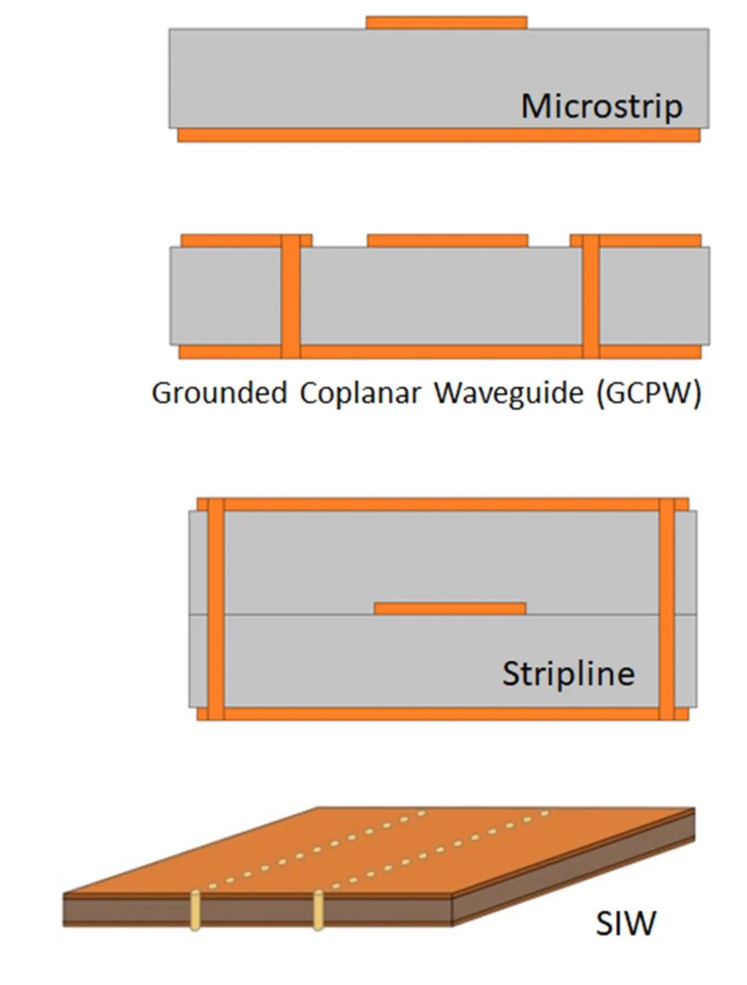
Figure 1 When transitioning to millimeter wave frequency, microwave circuit designers need to face the choice of at least four transmission line technologies at microwave frequency
Although the open structure of microstrip line is convenient for physical connection, it will also cause some problems at higher frequencies. In the microstrip transmission line, electromagnetic (EM) waves propagate through the conductor of the circuit material and the dielectric substrate, but some electromagnetic waves propagate through the surrounding air. Due to the low Dk value of air, the effective Dk value of the circuit is lower than that of the circuit material, which must be considered in circuit simulation. Compared with low Dk, circuits made of high Dk materials tend to hinder the transmission of electromagnetic waves and reduce the propagation rate. Therefore, low Dk circuit materials are usually used in millimeter wave circuits.
Because there is a certain degree of electromagnetic energy in the air, the microstrip line circuit will radiate outward into the air, similar to an antenna. This will cause unnecessary radiation loss to the microstrip line circuit, and the loss will increase with the increase of frequency, which also brings challenges to the circuit designers who study the microstrip line to limit the circuit radiation loss. In order to reduce the radiation loss, microstrip lines can be fabricated with circuit materials with higher Dk values. However, the increase of Dk will slow down the electromagnetic wave propagation rate (relative to the air), causing the signal phase shift. Another method is to reduce the radiation loss by using thinner circuit materials to process microstrip lines. However, compared with thicker circuit materials, thinner circuit materials are more susceptible to the influence of copper foil surface roughness, which will also cause a certain signal phase shift.
Although the configuration of the microstrip line circuit is simple, the microstrip line circuit in the millimeter wave band needs precise tolerance control. For example, the conductor width that needs to be strictly controlled, and the higher the frequency, the more stringent the tolerance will be. Therefore, the microstrip line in the millimeter wave frequency band is very sensitive to the change of processing technology, as well as the thickness of the dielectric material and copper in the material, and the tolerance requirements for the required circuit size are very strict.
Stripline is a reliable circuit transmission line technology, which can play a good role in millimeter wave frequency. However, compared with the microstrip line, the stripline conductor is surrounded by the medium, so it is not easy to connect the connector or other input/output ports to the stripline for signal transmission. The stripline can be regarded as a kind of flat coaxial cable, in which the conductor is wrapped by a dielectric layer and then covered by a stratum. This structure can provide high-quality circuit isolation effect, while keeping the signal propagation in the circuit material (rather than in the surrounding air). The electromagnetic wave always propagates through the circuit material. The stripline circuit can be simulated according to the characteristics of the circuit material, without considering the influence of electromagnetic wave in the air. However, the circuit conductor surrounded by the medium is vulnerable to changes in processing technology, and the challenges of signal feeding make it difficult for the stripline to cope, especially under the condition of smaller connector size at millimeter wave frequency. Therefore, except for some circuits used in automotive radars, striplines are usually not used in millimeter wave circuits.
Figure 2 The design and simulation of the GCPW circuit conductor is rectangular (above figure), but the conductor is processed into a trapezoid (below figure), which will have different effects on the millimeter wave frequency.
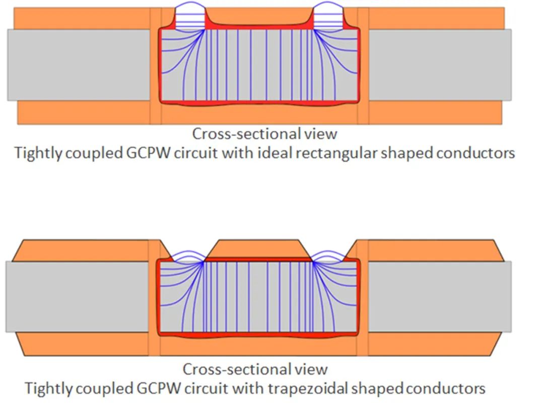
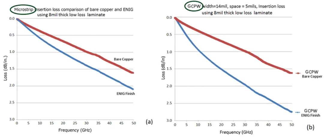
For many emerging millimeter wave circuit applications that are sensitive to signal phase response (such as automotive radar), the causes of phase inconsistency should be minimized. The millimeter wave frequency GCPW circuit is vulnerable to changes in materials and processing technology, including changes in material Dk value and substrate thickness. Secondly, the circuit performance may be affected by the thickness of copper conductor and the surface roughness of copper foil. Therefore, the thickness of copper conductor should be kept within a strict tolerance, and the surface roughness of copper foil should be minimized. Thirdly, the choice of surface coating on GCPW circuit may also affect the millimeter wave performance of the circuit. For example, the circuit using chemical nickel gold has more nickel loss than copper, and the nickel plated surface layer will increase the loss of GCPW or microstrip line (Figure 3). Finally, due to the small wavelength, the change of coating thickness will also cause the change of phase response, and the influence of GCPW is greater than that of microstrip line.
Figure 3 The microstrip line and GCPW circuit shown in the figure use the same circuit material (Rogers’ 8mil thick RO4003C ™ Laminate), the influence of ENIG on GCPW circuit is far greater than that on microstrip line at millimeter wave frequency.
Post time: Oct-05-2022


