Let’s first consider the question of why millimeter waves are used. First, there are many benefits to increasing the operating frequency of most well-established systems, including the potential for increased available bandwidth, improved resolution and directivity for a given antenna aperture. This means smaller, lightweight systems in communication systems , can provide greater transmission capacity, or radar or imaging systems can achieve higher resolution. For the latter, millimeter and/or submillimeter systems are often used to achieve the resolution required for image recognition, or to identify exposed objects through spectroscopic properties.
Furthermore, at millimeter wavelengths, the atmosphere has some unique transmission properties. Millimeter wave wavelengths are generally considered to be in the 1 to 10 mm range or frequencies in the 30 to 300 GHz band. Some so-called window frequencies are able to pass through dust, smoke, fog, and the atmosphere, where atmospheric attenuation is minimal and transmission range is maximized in these frequency ranges.
In the medical field, terahertz (THz or submillimeter wave) diagnostic tools use organo-metallic molecular markers as tracers in the study of cancer cell structures. On the other hand, in order to achieve non-invasive skin cancer diagnosis, millimeter wave skin Imaging passive scanners are also in the research phase.
The application of millimeter wave
After introducing the background, let’s examine the application fields of millimeter waves. Of course, it is difficult to make a very comprehensive review of such a broad topic in a short article, because there are too many related topics. If there are any omissions, I apologize to the researchers and manufacturers of related topics.
In millimeter wave applications, one area that needs special emphasis is terrestrial and satellite communication systems and millimeter wave band terrestrial communications. Cellular telephony and data link infrastructure are by far the largest commercial applications of mmWave systems. So-called “backhaul” is utilized in these systems to provide line-of-sight connectivity between system nodes. Using this technology to create a wide-area wireless network that is largely independent of existing infrastructure could make mmWave systems attractive to developing countries. Currently, various players compete in the microwave/mmWave wireless market, dominated by high-capacity mmWave radios at the most common frequency of 38 GHz.
For greater capacity, frequencies in the 50 to 60 GHz band can be used in “hot spots” or “last mile” locations such as airports, train stations and temporary uplinks for broadcasts and special events. Electric companies such as Proxim Wireless2 provide high-capacity point-to-point fiber-optic compatible radio systems within the range of 0.25 to 1 km. The system works in the unlicensed 57 to 64GHz frequency band, as shown in Figure 4. Data rates are available from 125Mbps to 1.25Gbps using modulations of varying complexity. The interface in the point-to-point wireless network adopts standard interface specifications, such as OC3 (155Mbps) and OC12 (622Mbps).
Depending on the network, a mix of frequencies can be chosen to balance capacity, coverage and infrastructure cost. Although more and more advanced modulation methods greatly expand the capacity of a given link, the demand for greater bandwidth not only keeps the market for existing radio equipment to maintain strong growth, but also ensures the market prospects of emerging E-band wireless connectivity products. According to the recent FCC authorization, the E-band is in the 71 to 86GHz frequency band, which enables data to be transmitted at a rate of 1 to 10Gbps over a range of several miles over a wireless link. Applications include bridging with fiber optic networks and providing backhaul channels for mobile and fixed wireless networks. The development of the emerging E-band depends on near-term investments, performance improvements and corresponding reductions in the cost of mmWave ICs.
Another necessary factor for building a commercially viable system is the existence of a compatible high-precision, low-cost antenna. A higher gain is required to obtain a greater transmission distance, and the high gain is provided by a precise parabolic reflector. Companies such as Radiowaves are leaders in the manufacture and testing of high-frequency antennas for digital radios. Generating dense patterns at millimeter wave bands requires precise antenna surface and feed position tolerances, and requires complex antenna test distances to be set.
Millimeter wave satellite communication
To a certain extent, the deployment and development of millimeter-wave satellite communication systems reflect the deployment and development of ground systems. The most bulky applications include Ka-band (26.5 to 40 GHz) SATCOM terminals, in fact frequencies around 20 and 30 GHz are used in this system for downlink and uplink respectively. Conventionally, satellite terminals use higher link frequencies to take advantage of their smaller, easier-to-deploy antennas for the same gain. The biggest challenge for ground terminal suppliers comes from integrating MMIC technology into larger commercial applications. This is largely a matter of engineering and design methods for semi-automated production. An excellent reference document R.ALMR.5 describes this technique.
There is every reason to believe that with the investment in supply in Ka-band satellite technology and the experience with the current mass market production, higher frequency applications will be successful in the market, and eventually live TV in the Ku-band (10 to 14 GHz) will succeed.
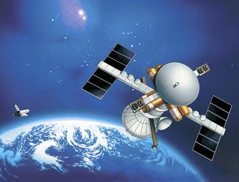
In addition, given the critical role of secure global communications in national defense, high data rate satellite systems have been deployed and are continuing to be developed, some of which have uplink frequencies of 44 GHz. One example is the US MILSTAR satellite network, which has been in operation since 1994 and has undergone a complete upgrade (MILSTAR II is shown in Figure 5), which is able to provide higher data rates (up to 1.5 Mbps for 192 channels), anti-jamming, and inter-satellite cross-links at 60 GHz. The latest satellite was launched in 2003.
Research on the MILSTAR ground terminal is still ongoing. Research is focused on high-performance multi-frequency millimeter-wave converters and antenna systems. These studies include production techniques that use automated manufacturing to ensure high reliability and low cost.
Scientific applications of millimeter waves
The issue is too broad to be fully addressed here. So only two examples are given, from which we can see the great contribution and rapid development of the millimeter wave system. As a first example, millimeter-wave radio astronomy has become an important research field in the last 30 years since the first identification of various molecules from extragalactic molecular clouds using millimeter-wave spectral resonances. Today, increasingly sophisticated terrestrial millimeter-wave and submillimeter-wave devices are becoming shared tools for the scientific community. For its size alone, the Atacama Giant Millimeter Array (ALMA), currently under construction in the high-altitude desert of northern Chile, is noteworthy
The millimeter and submillimeter radio telescope is an interferometer consisting of 64 satellite dishes with a diameter of 12 meters, each covering a wavelength range of 0.35 to 10 millimeters. Its resolution will reach 1 nanosecond, an order of magnitude higher than the Hubble Space Telescope, and it can also be used as an imaging tool. The goal of scientists using this device is to explore the cold universe, where the temperature of various substances ranges from 3 to 100K. As the temperature rises, the spectral lines of these substances also gradually rise in the millimeter wave range. This distribution will enable the study of the molecular gas and dust that clump together to form stars, planetary systems and galaxies.
From a historical perspective, radio astronomy has given rise to technological advances in high-frequency receivers, high-frequency antennas, and high-frequency spectrometers on which other research must rely. In order to use observation time more efficiently, multi-channel imaging becomes very important. This, to a certain extent, promotes the development of electronically scanned array sensors to other fields.
Also worth mentioning is millimeter-wave remote sensing technology, especially millimeter-wave satellite remote sensing of the Earth’s atmosphere, which provides valuable information by mapping the Earth from space. Atmospheric sounding is typically accomplished with payloads covering the frequency band 10 to 183 GHz, designed to measure blackbody leakage from Earth or planetary systems. Beginning in the 1980s by NOAA-NASA, early satellites carried multispectral millimeter-wave radiometers. This payload is usually launched with and in addition to available multispectral infrared and optical imaging weather instruments. Since land, water, air, and ice have different apparent color temperatures, in some cases these features can be separated and in some cases uniquely identified. Figure 7 shows the winter/summer ice cover map obtained by microwave remote sensing.
In addition, atmospheric temperature detection can use the 60 GHz resonance characteristics of oxygen, and can also use water vapor to measure its spectral profile. These methods tend to have low spatial resolution (usually thousands of meters away from the spacecraft), limited to some extent by the available antenna aperture.
The direction of new development is to increase the range of detectable atmospheric components, which can be achieved by expanding the range of detectable frequencies while using geosynchronous satellites to improve static coverage. With respect to Earth imaging using geostationary satellites, there is a challenge in meeting the antenna size requirements (approximately 2 to 3 meters in diameter) for reasonable resolution and the difficulty of scanning such a large antenna in order to provide the required ground coverage. Possibly a mechanical scanner as used in mmWave passive imagers (discussed later) can solve this problem.
Millimeter wave radar
The commercial automotive radar system is largely developed from the defense radar system, which uses millimeter wave sensors and has been developed. The original systems were based on Dirichlet effect diode technology, which is now becoming a major application area for GaAs MMICs. The commercial forward-looking radar system works at 77GHz, and its detection range reaches 200M. These radars are marketed as autonomous cruise control (AAC) radars.
Further expansion of this capability would require major improvements in radar performance (such as classifying targets with a small probability of false alarm). Despite the limitations of the current system, casting suppliers still compete fiercely in the market, making every effort to cooperate with system designers and system integrators. Most mmWave device foundries are working with radar designers to meet the needs of their customers, which are basically automotive equipment manufacturers. Due to the high cost of integration, providing an “add-on” package is usually not cost-effective, so these radars need to be designed into the system.
Although GaAs technology provides a perfect solution for mmWave applications, improvements are still needed (for example, in product-level design, which does not depend on finished product adjustments). Although MMIC vendors such as UMS have made considerable progress in multi-chip packaging methods, the 77 GHz packaging task remains competitive.
Another area that needs further development is the companion VCO solution for FMCW radar. The original 0.25μm PHEMT VCO has been replaced by an HBT design using a 0.15μm process that offers better low frequency phase noise performance with a higher cutoff frequency; typical performance of -85 dB/Hz at 100kHz offset is a credible one. As with most system-related developments, the system’s challenge is to achieve the optimum combination of functionality and manufacturing cost that will support the growing market.
Post time: Jul-27-2023


